GPIO
혼자 독립적으로 동작하는 형식이라면 굳이 고민이 필요 없지만, 보통은 외부 장치들과 GPIO로 연결되어 제어를 해야할 환경이 대부분이다.
SD CARD까지 지원하니 GPIO가 사용할 수 있는 것이 거의 없다시피 한다. 필자는 SD CARD를 사용하지 않아서 꽤 많은 부분을 사용할 수 있었다.
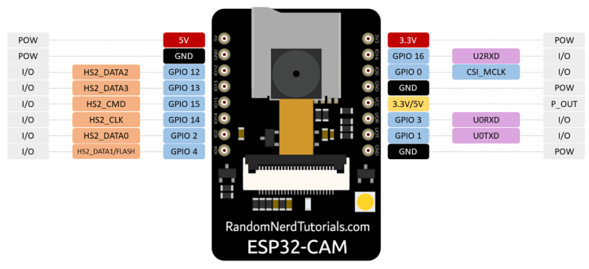
These pins are internally connected to the microSD card reader:
- GPIO 14: CLK
- GPIO 15: CMD
- GPIO 2: Data 0
- GPIO 4: Data 1 (also connected to the on-board LED)
- GPIO 12: Data 2
- GPIO 13: Data 3
If the pins are not being used for microSD card, you can use these pins as regular inputs/outputs. All these GPIOs are RTC and support ADC: GPIOs 2, 4, 12, 13, 14, and 15.
GPIO 4는 전면 Flash LED와 연동되니 빼고, 건너편 GPIO16까지 해서 6개의 GPIO를 확보할 수 있다.
#define CAMERA_DIR_GPIO_NUM     2
#define AUDIO_INPUT_GPIO_NUM    16
#define SHUTTER_GPIO_NUM        13
#define PTTN_GPIO_NUM           15
필자는 이번 프로젝트에서 위와 같이 4개를 사용했다. 매번 UART 로그를 확인하기 쉽지 않다면, 전면 LED는 에러 상황이나 동작 종료 같은 알림용으로 사용하면 매우 편리하다.
void front_led_flash()
{
    pinMode(4, OUTPUT); // Set the pin as output
    digitalWrite(4, HIGH); //Turn on
    delay(50);
    digitalWrite(4, LOW); //Turn off
}

void front_led_flash_twice()
{
    front_led_flash();
    delay(50);
    front_led_flash();
}

void front_led_flash_third_time()
{
    front_led_flash();
    delay(50);
    front_led_flash();
    delay(50);
    front_led_flash();
}
GPIO 33 is an on-board LED, that is next to the RST button. That on-board LED works with inverted logic, so you send a LOW signal to turn it on and a HIGH signal to turn it off.
뒷면에 전면 LED와는 상대 안되게 작은 RED LED가 GPIO33과 연결되어 있다. 이 부분도 따로 활용할 수 있겠지만, Connector Board를 제작해서 연결하는 바람에 사용할 수가 없는 환경이었다.